Rectifier


Mr.Praveen Prasath .
" "
ABOUT
Electronic Devices have become an essential part of our life and it’s almost driving our daily needs like communication and complex tasks like computing. The Electronic components work on Direct Current which is represented as DC. The Smartphone or the Desktop which you are currently viewing this article is somehow dealing with DC for proper working of all passive and active components inside it. In DC it is either (+) or (-).
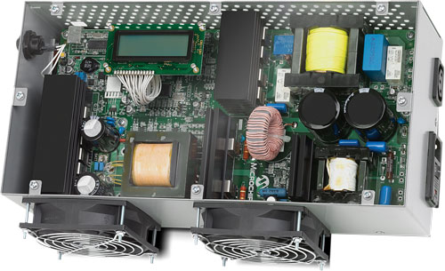
In earlier posts, we have seen the basics of AC and DC. The commercial electricity which we use in our houses is Alternating Current (AC) and the Fan Lights and Electrical appliances run on 230V AC. You can’t use that directly to charge the Smartphones or to drive Computer, You need to convert it into pure DC power. Your smartphone charger and Power Supply unit in Computers do this specific job of converting AC into DC. This process is called Rectification. So getting into the rectifier working first let us understand the AC supply. In AC the current moves back and forth like a Sea Waves and it changes every time, In India, the frequency is 50Hz so the current direction changes 50times forward and backward every second and it is in the sinusoidal waveform.
How we convert AC into DC?
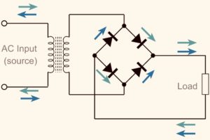
We use Electronic components to create a converter that converts AC into DC. The simplest way to achieve is to use a Bridge circuit. Bridge rectifier is a full-wave rectifier and it is also known as Full Bridge Rectifier. This converts the AC into Pulsating DC and again we use a capacitor in parallel at the output to filter the DC output to achieve pure DC.

Bridge Rectifier
» We use a diode to create a bridge circuit. The diode only conducts during forward bias and during reverse bias, the diode doesn’t conduct.
» Let us again consider the AC supply is a sea wave and it is going back and forth and now we have a diode which we can imagine as a pipe which has a shutdown valve and it allows only to pass the sea-waves and it shutdowns the valve when the sea-waves tries to pull back the current. Just consider the above as an example and now we arrange the diode in such a way that the output conventional current always lies in the forward direction which is positive to negative. The below circuit represents the Bridge.
» After the rectification from Bridge rectifier, the output current is in pulsating DC so we add a polarized capacitor in parallel to the output to constant the voltage and smoothen the curve and the below video is simulated for better understanding and the orange line shows the pure DC output.
In this process, the output voltage depends upon the supply voltage and Diode characteristics. This is an Uncontrolled Rectifier and the output voltage can’t be manually adjusted so we use the power electronic component in place of the diode to achieve Controlled Rectification. We use high-speed semiconductor devices like Thyristor and MOSFETS in order to achieve Controlled Rectification.